

EWOD refers to the modification of wettability of a liquid drop placed on a hydrophobic and dielectric coated solid surface with an applied electric potential.
Single- Plate EWOD Configuration
(Sessile Drop Configuration)
In single plate EWOD configuration, a drop of electrolyte (polarizable or conducting) is placed on a solid electrode which is coated with layers of dielectric and hydrophobic. This dielectric layer insulates the liquid drop from the solid electrode and prevents electric current passing through the system. Before electric potential applied, the charge build-up over the surfaces is negligible (Figure 1.1 (a)). After electric potential applied, charges are induced over the surfaces (Figure 1.1 (b)). This charge redistribution decreases the interfacial energy between the solid surface and the electrolyte. Decrease in interfacial energy results a decrease in contact angle.
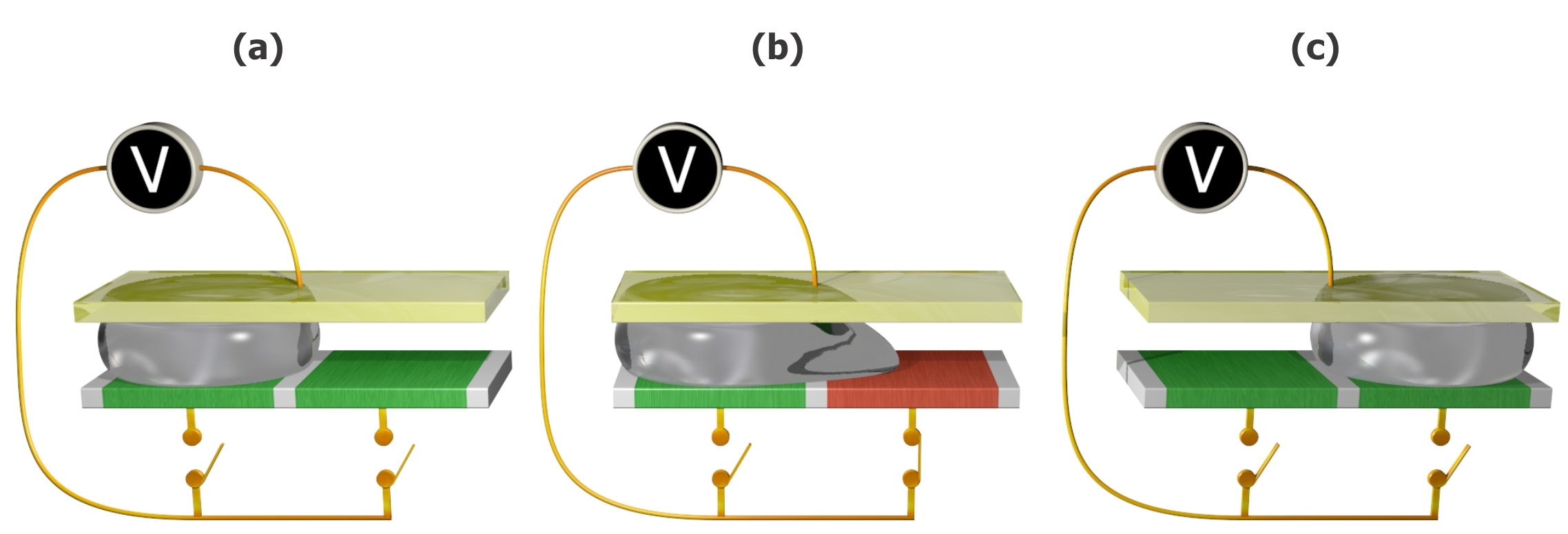
Parallel-Plate EWOD Configuration
A drop of electrolyte is sandwiched between two plates assembled in a parallel structure. The top plate consists of a grounded electrode which is coated with a layer of hydrophobic insulation. Bottom plate consists of array of distinct electrodes that can be actuated independently from outside voltage source. The bottom plate is covered by thin layers of dielectric and hydrophobic insulation. A uniform spacer gap is maintained in between top and bottom plates. A precisely controlled volume of liquid is generated from a liquid reservoir such that the footprint of the liquid drop is approximately equal to the top surface area of the electrode. The gap between two electrodes is controlled to be few microns such that the liquid drop is in contact with the adjacent electrodes. Under applied electric potential to adjacent electrode, the decrease in contact angle generates a pressure gradient across the liquid drop (Figure 1.2b). This pressure difference moves the liquid drop from the existing electrode to adjacent electrode (Figure 1.2c). Sequentially actuating individual electrodes one by one, the liquid drop can be moved in any direction along an array of electrodes.
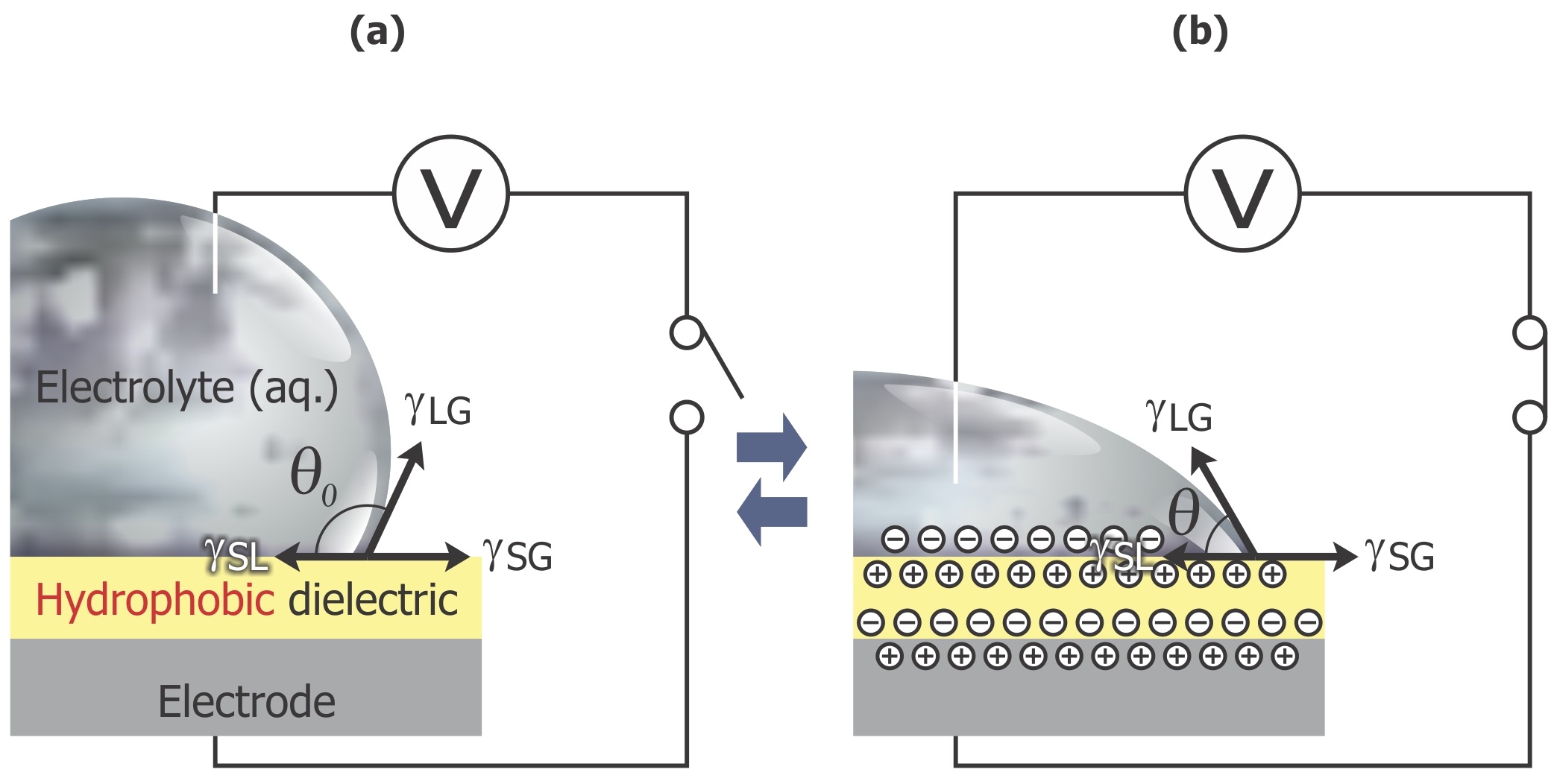
Figure 1.1. Illustration of EWOD, (a). Before applying electric potential, (b). After applying electric potential